Conversion Timeline Review
Here is the complete timeline of the conversion, from the frontpage Slideshow
Purchased BMW 320i on 09/25/2013
Internal Combustion Engine (ICE) removed. 01/06/2014
Weighing the car de-iced, cleaning the engine compartment, Electric motor fitting. 02/08/2014 - 03/18/2014
Spinning the rear wheels with electric components. 05/19/2014 Four months after ICE removal!
Spoofing the Instrument Cluster 6/27/2014
Battery Conditioning System 7/17/2014
Battery Boxes Fabricated and Installation started. Contactor Box for the Battery Connections. 8/17/2014
Delphi DC/DC Converter Upgrade 3/27/2015
All Batteries connected in rear seat boxes and strapped up in trunk box 9/03/2015
Wiring cross-over box 11/20/2015
Engine compartment components installed and wiring finished. 2/4/2016
All electric drive components installed. Spinning the wheels, preparing for the test drive. 5/10/2016
First test drive! 10/07/2016 Two years and 9 months from ICE removal
Major Milestone. Vehicle passes Massachusetts Inspection 6/19/2018 Now Drivable on the road! Total 4.5 years for the complete conversion.
Major Upgrade. Scott Drive Inverter 6/12/2019
Major Milestone. Commuting to work in the ElectricBMW320E 7/25/2019
Upgrades: New Wheels, Tires and Suspension. Scott Drive Installation. 8/10/2019
Major Upgrade. Chevy Bolt Battery Modules 10/18/2020
Upgrades. New Paint, Winter Tires and Wheels 11/15/2020
Instrument cluster update 5/20/2024
Battery Maintenance System (BMS) from 7/03/2023 to present.
Supplier Listing
Listing of the suppliers I used for my build. Download the spreadsheet here. Any of the first three suppliers can supply all the components needed for a converstion. Price and availablity are the main differneces. The other suppliers are for all the other items that are required for restoring a car or building electronics.
320i Specs and EV Design
This 320i in fantastic condition was found on Ebay. The car had been stored for more than 15 years which is why it is in such good condition. It has many features that make it any ideal doner car for an electric vehicle conversion. First, it is very light, about 2500 lbs curb weight. Second, it has lots of room for placing batteries. Third, it basically has no computer systems for controlling the car. This BMW 320i is actually a 320i"s" for sport version. It has an upgraded suspension, a limited slip differential and the seats in the passenger compartment are "Recaro" seats - very tight bucket seat. Here is the link on Wikipedia for the 320 series.
Proform Vehicle Scale weight distribution after ICE component removal:
Left front = 403 lbs; Right front = 363 lbs Total = 766 lbs
Left rear = 509 lbs; Right rear = 502 lbs Total = 1011 lbs
Total weight = 1776 lbs, so based on a curb weight of 2452 lbs that means 675 lbs for the ICE components. Probably not all that weight just off the front end. Some weight was for the gas tanks and exhaust and drive shaft.
Battery placement
18 cells in front between wheel wells = 80 lbs
Siemens motor and DMOC 645 = 320 lbs
48 cells under rear seat = 213 lbs
54 cells in trunk, over the rear axle = 240 lbs
Brusa charger in trunk = 13 lbs
Front added weight = 80 + 320 = 400 lbs
Rear added weight = 213 + 240 + 13 = 466 lbs
Front will also have water heating and cooling, brake vacuum and DC-DC converters, that will be at least 60 lbs and some of the battery weight under the rear seat will probably translate to the front wheels.
Just the batteries and motor and components weight added to the de-ICE weight gives 2642 lbs. The transmission, clutch and drive shaft weigh 108 lbs. Of course the battery boxes will add weight. The total conversion weight still should be well under 3000 lbs.
Post build note: weight is 2860 lbs with a 48/52 front/rear weight ratio.
Here is the design layout of most of the components for the engine compartment.
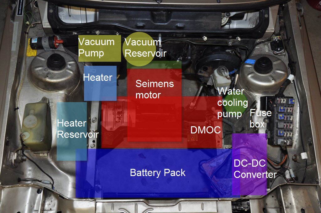
On an EV electric motors have to provide resources like heating and vacuum that were available on the ICE. So there is a vacuum pump and reservoir for the brakes and cabin controls and a heating unit and reservoir for the fluid to heat the cabin. The Siemens drive motor does not need much cooling, but the DMOC inverter does need to be cooled. So there is a pump and heat exchanger. The heat exchanger is a small radiator and it will sit directly behind the front grill. The radiator needs a fan for when the vehicle is not moving. The 320i has a fan that was intended to cool the evaporator coil for the air conditioning, even though there is no air conditioning on the car. But I found that the fan draws 25 Amps! A heat exchanger from Derale will be used instead. It only draws 5 to 6 Amps.
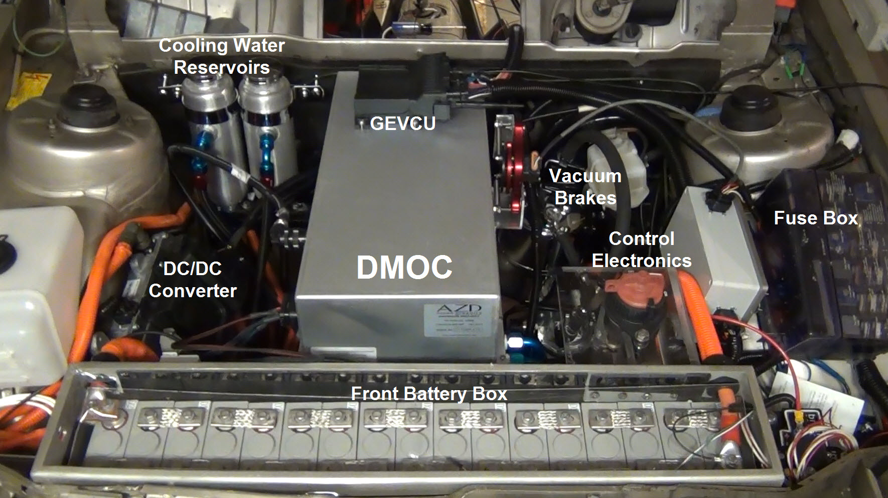
Below is how the actual build looks like. The Siemens motor is below the DMOC so it cannot be seen. Water pumps are also below as well as the main contactor box. There is no heating reservoir as I am using PTC heater elements to heat the passenger compartment.
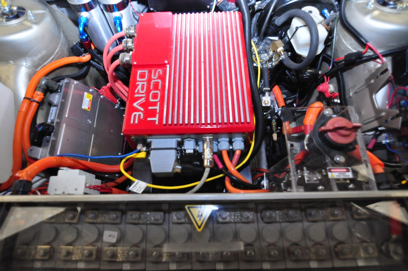
Below is the latest upgrade. The DMOC and GEVCU were replaced with a Scott Drive controller system. The Control Electronics have also been removed as all that functionality is contained in the Scott Drive.
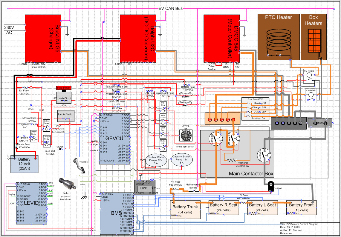
Below is the wiring schematic for the complete design. A larger view of this diagram can be seen in the photogallery.
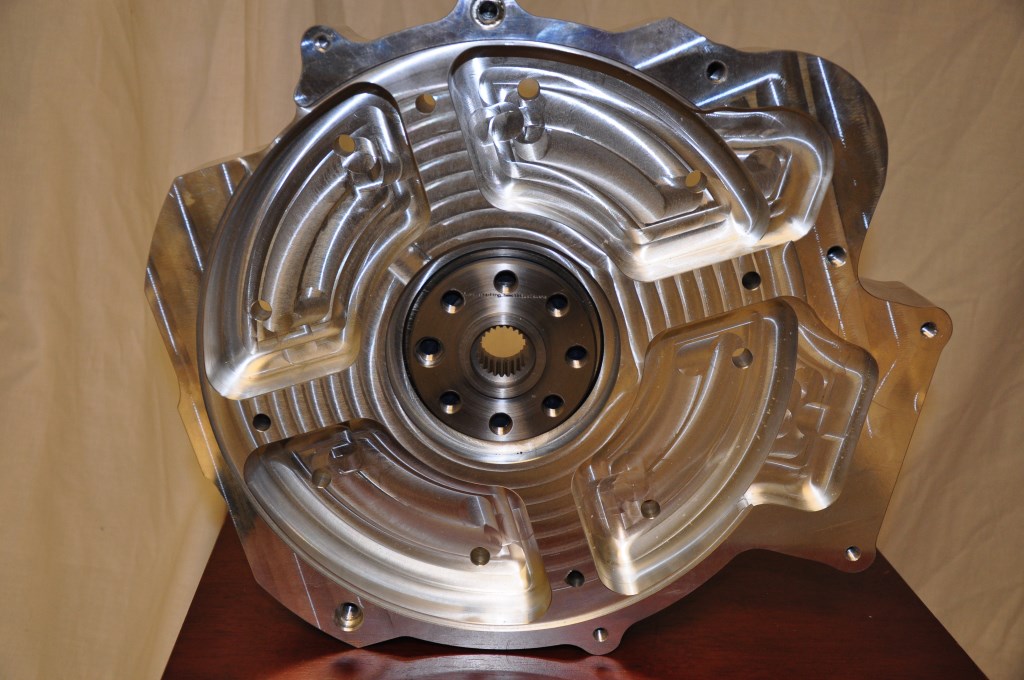
I plan to use the 5-speed manual transmission from the 320i for the EV build. That will be used with a racing clutch from Summit Racing. A high torque clutch is required because of all the torque the electric motor generates at zero RPM. If the clutch is not strong enough the vehicle might not even move and the clutch will just spin and burn. The clutch and flywheel will be spin balanced together. That is done to reduce drivetrain vibrations which are very noticeable in a electric drive vehicle because the motor does not vibrate like an ICE. The balancing is being done by a local company called Lindskog Balancing. The 5-speed transmission will be coupled to the Siemens motor using a bell housing adpater made by RebirthAuto and a spline adapter made by EV West shown below. The adapter connects the spline drive shaft of the electic motor to the flywheel, clutch and transmission. The clutch side is shown.
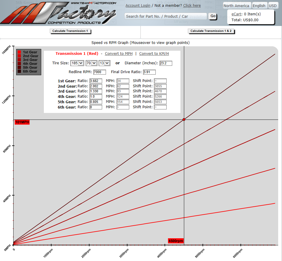
On the 2/7/2014 issue of the Vblog at EVTV there was a discussion of gear ratios, RPM and speed. Below is a graph of the calculated speed as a function of RPM for the 320i with the current gear ratios and tires. It shows that at 4500 RPM in 5th gear the 320i should be capable of over 100 MPH. This graph is from TeammFactory.com
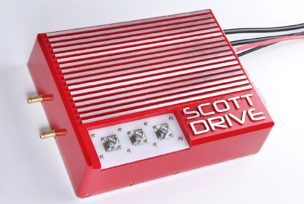
Scott Drive SD100
Although I was one of the initial designers of the GEVCU (see EV Design), the combination of the GEVCU and the DMOC proved to be too unreliable. After I finished the conversion and started driving the car, several times the GEVCU will fail to operate. My experience was not unique - other GEVCU users had similar problems. Fortunately for me I was never stranded anywhere when the GEVCU failed, either in my garage or driveway. But I was concerned that I would be stranded somewhere as I was using the car for a semi daily driver. I wanted a more reliable, commercial system. Several years ago I reviewed a Scott Drive SD100 inverter at EVWest. I purchased that inverter and in 2019 I installed it in the car. It took about 4 months to install. I had to make a completely new wiring harness for the control signals, modify the plumbing for the water cooling and build a new mounting system. Initially it did not work correctly. It would turn the Siemens motor in reverse. The software GUI shown below had a setting that you could change the motor direction with, but the software would crash every time that setup was saved. It turned out the Scott Drive needed a firmware update that I had to get from Scott Osborne in New Zealand, the maker of Scott Drive. Once that was taken care of the inverter worked as advertised. It is a 100KW inverter so it matches the Siemens motor well. It has a large number of inputs and control signals available. Just like the GEVCU it has the ability to put the motor in regeneration for braking. If you want to learn more about the SD100 and other Scott Drive inverters you can find that here.
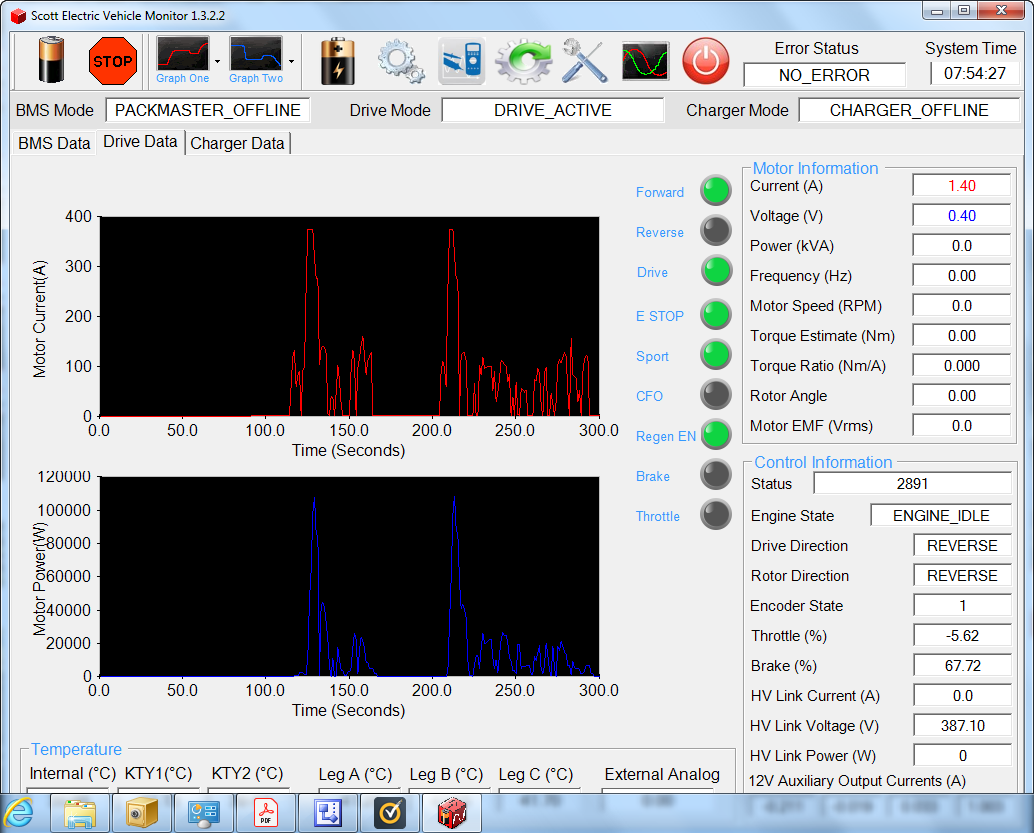
Software GUI used to setup, calibrate and monitor the Scott Drive. If connected to a laptop during driving the performance data can be captured as shown below. Although the inverter is capable of 100KW continuously it is also capable of up to 150KW peak.
Chevy Bolt Batteries and BMS
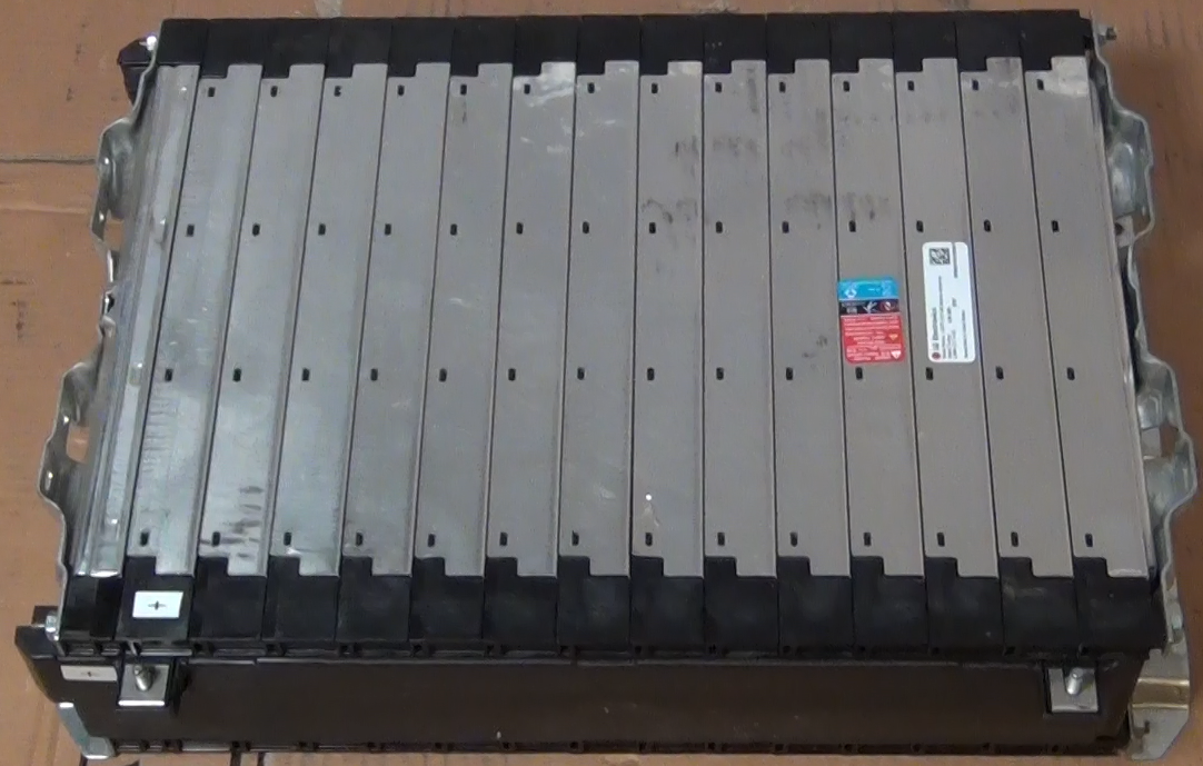
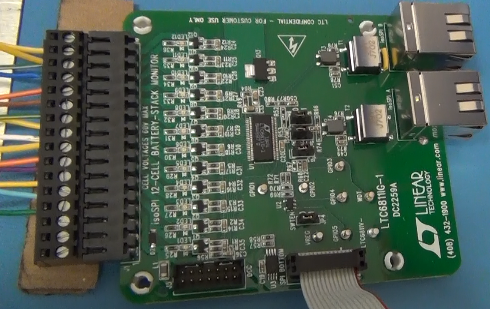
To get more driving range the batteries were upgraded in early 2021. The upgrade batteries used are the Chevy Bolt 5.94kW-h module shown in the picture below. These modules are made by LG Electronics and are NCM (Lithium Nickel Manganese Cobalt Oxide) chemistry. Each module has a 180AH capacity and the 9 modules that will be used gives a 53kW-h battery capacity. For a 85% discharge that provides 45kW-h of driving capacity. At the measured power consumption of 292W/mile by the vehicle that capacity should provide just about 155 miles driving range. A great feature of these modules is that they are already wired for a Battery Maintenance System (BMS). Each module has 10 cells and there are connections to each cell on the module. The connections are on a pair of connectors at one end of the module. The Chevy Bolt uses a central processing unit for the battery maintenance so in the Bolt each battery module has a pair of cables that runs back to the central controller. The cables with the corresponding connectors already attached were obtained form Chevy Parts Online and used to make cables to connect to a local BMS controlling circuit. Each battery module will have its own BMS controller. This is easier than running wires from each module up to the engine compartment. Although between the wires from one module the most voltage would be 42V (full charged battery) the wires will have the full pack voltage, with respect to ground. Local BMS control will be safer at this point in the 320e build. A BMS demo board, the DC2259B made by Analog Devices was initially tested to use for the module BMS. The connections to the battery module and a BMS demo board are shown in the second and third photos below. Although the new batteries are bigger and weigh more than the CALAB cells the new batteries will only increase the weight of the car 100 lbs but increase the driving range by 2 times!
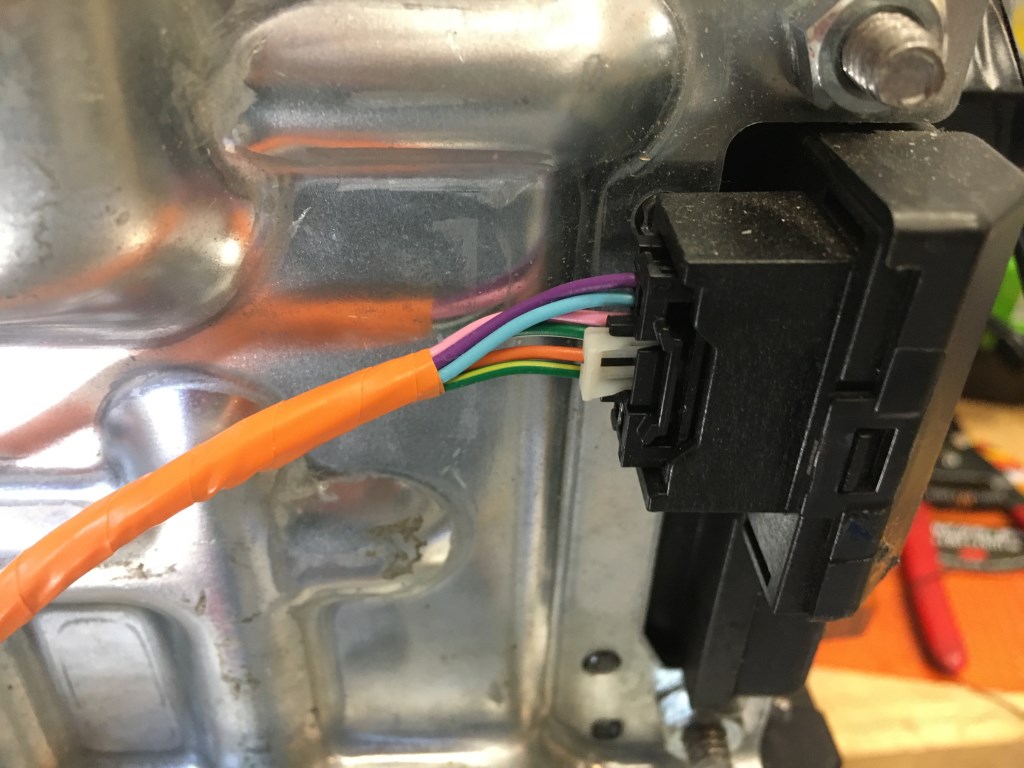
BMS connection on battery module. These connectors were obtain from a Chevy Bolt battery wiring harness that was purchased online.
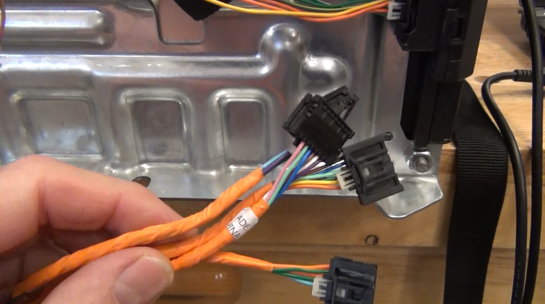
Two connectors are required to connect to all the battery cells in the module. A DB25 connector is used for the wires coming from the battery module to make connection the BMS demo board.
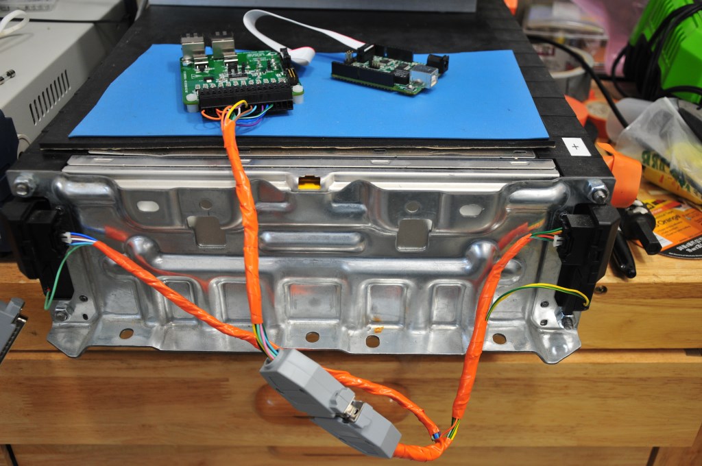
DC2259A BMS demo board that demonstrates the LTC6811-1 BMS integrated circuit.
Page 1 of 3